VK3RTV ATV Repeater Pictures
| DESCRIPTION | PICTURE |
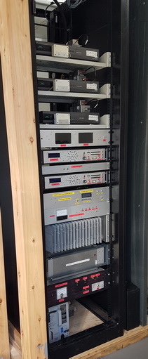
| New VK3RTV rack. |
|
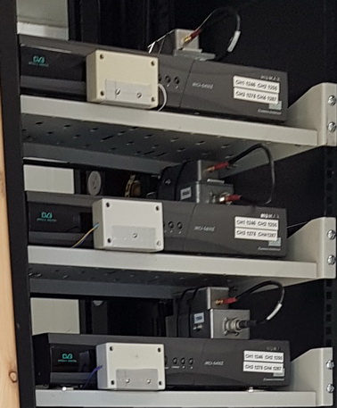
3 X HUMAX digital satellite receiver (now swapped out to combo DVB-S2/T2 receivers), 1 for each input.
IR transmitters in cream boxes on front of each receiver enables remote control like selecting signal reports. |
|
2 monitors for monitoring output video for VK3RTV1 & VK3RTV2
Audio controller for multiplexed channel VK3RTV2
Video player. Plays video for beacon mode etc
Audio controller for multiplexed channel VK3RTV1 |
|
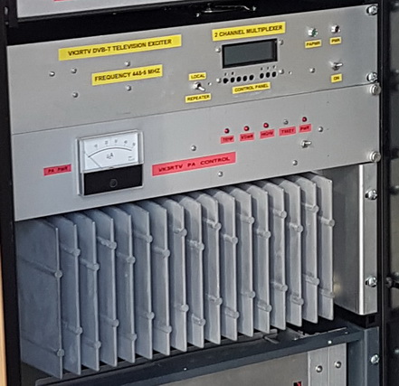
2 channel multiplexed DVB-T exciter
Amplifier controller
Power Amplifier |
|
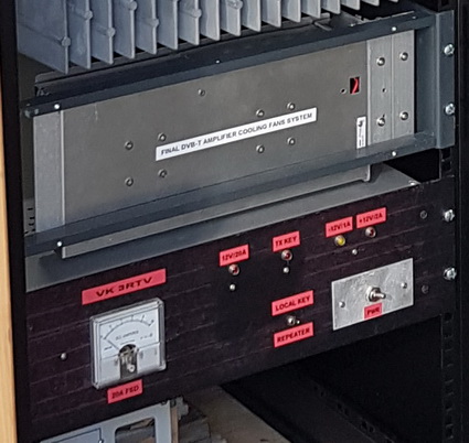
Power Supply and cooling fan controller |
|
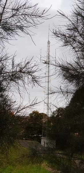
| Overall view of current tower installation |
|
Business part of the tower.
RX antennas are the 3 rectangular boxes mounted on the tower under the outriggers, 1 on each leg of the tower.
TX antenna is the phased array holding prime position at the top of the tower. |
|
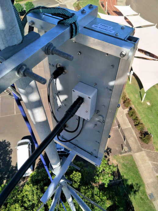
Rear view of one of the RX antenna's. (All 3 RX antennas are identical). |
|
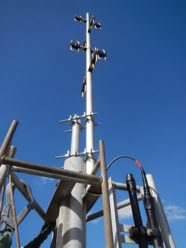
TX antenna at the top of the tower. |
|