
1.2 GHz (23 cm) 2 W RF amplifier
With a modified Motorola SHL7008 hybrid module
A collection of info by VK3GE, VK3QL, VK3BFG, VK3BCU, VK3YLH, VK3IE, VK3TRX, VK5YYY
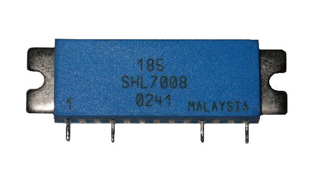
Technical information for SHL7008
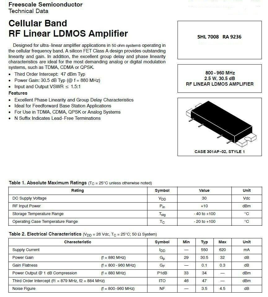
A later version of the same module is the MHL7236 (practically identical specs). Click here for the MHL9236 data sheet.
The modification
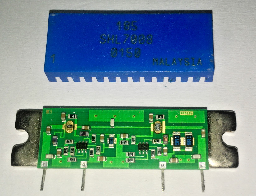
First, take the module apart. The blue cover is glued at each corner — use a screwdriver under a corner and some leverage to pop it off. Beware: there are tiny components inside that are easily destroyed. Do not drop the module with the cover off, do not touch the fine internal wires, and be quick with any heat application.
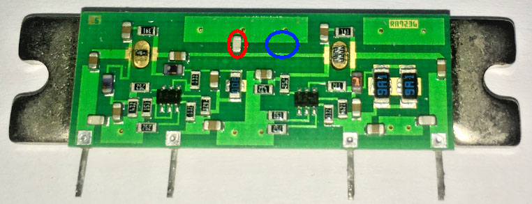
SHL7008 interior with cover removed
Move the chip capacitor from its original position (red oval) toward the output side of the module to somewhere in the blue oval — exact placement is not overly critical. The ideal position has varied between builders, but the blue oval will get you very close.
SHL7008 interior — capacitor move
Glue the blue cap back on the module. That is the complete modification — all the rest is mounting and powering.
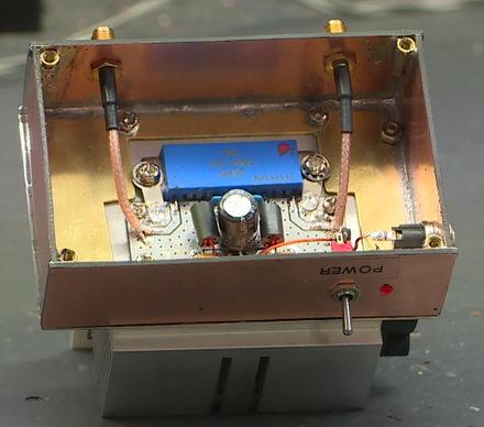
Practical implementation
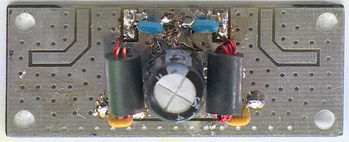
Mount the module in a metal box (23 cm RF requires a metal enclosure — no plastic) with heat transfer compound to maximise heat dissipation. Use whatever connectors suit (SMA, BNC, N). If the box is not sized right, connectors can be soldered directly to the PCB with semi-rigid coax.
Good earthing of the module and PCB is essential. Add an earth strap from the PCB to the module at each mounting point.
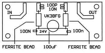
Power supply: 24 V at ~0.5 A. A 13.8 V shack supply can be used with an internal buck/boost converter (~$4–$5 AU delivered). Enter the supply via a feed-through capacitor, or use a 1 nF ceramic chip bypass capacitor at the supply entry point.
Pins 2 and 3 of the modified module should have a single-hole ferrite bead on each leg next to the module. Additional bypass capacitors: 100 µF electrolytic or tantalum, 2× 10 nF chip, 2× 100 nF chip, 2× 100 pF chip. PCB design by VK3BFG.
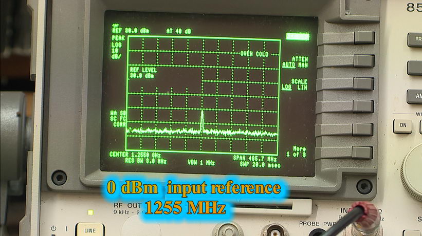
Testing
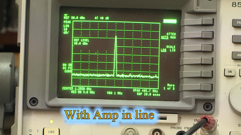
Check your work, cross your fingers. Connect a 24 V supply (or 13.8 V with buck/boost converter). Apply ~0 dBm (1 mW) input at your desired 23 cm frequency. Output should be around 1.7–1.9 W. Input of 3 dBm (2 mW) should produce ~2.5 W output.
Around 2.5 W is the maximum while remaining linear. You can slightly adjust the capacitor position if the output is not as expected at the desired frequency.
 |
 |
| Test frequency: 1253 MHz Reference level: 0 dBm (1 mW) |
Output: 33 dB gain over input |
The amplifier can be used across the entire 23 cm band.